There is an implementation gap between standard and failsafe implementations of the timers on Siemens PLCs. In fact, the standardised IEC timer procedures include only a blind pulse generator TP, delayed raise TON and delayed reset TOF. The extended features like auto-restart and pulse preservation implemented in STL (SE instruction) are not implemented due to the restrictions of the failsafe design standards. Moreover, on legacy systems like SIMATIC S7-300, the limitations are even more strict. For example, the inputs of an IEC timer block on the S7-300 series PLC cannot be linked to the branched safety chain, and the outputs support only single assignment operation as a receiver cause the standard requires preservation of the logical output and restricts its transposition to RLO (Result-of-Logical-Operation) system bitfield. With this, migration of the legacy STL programs to the modern failsafe FBD programs becomes a non-trivial task, especially in the presence of the requirements to keep the program strictly deterministic and explainable. Here below, the example task of migrating an STL procedure, including the SE pulse extended timer instruction to Failsafe FBD procedure.
Target Setting
Given the procedure below, written in STL:
    AN    "BARRIER_CROSSED"         // Normal-closed optical barrier crossed
    L     S5T#10S
    SE    "T_BARRIER_TIMEOUT"       // Extended timer with auto-restart feature
    AN    "T_BARRIER_TIMEOUT"       // Non-zero timer state query
    CU    "BARRIER_COUNTER"         // Increasing counter at barrier crossing
    L     "BARRIER_COUNTER"
    L     1
    >I                              // Comparison
    S     "BARRIER_ZONE_VIOLATION"  // Set violation flag
The task is to migrate this procedure to Failsafe FBD description language.
Solution
Initial Condition Analysis
The procedure implements a simple algorithm that increments the BARRIER_COUNTER counter register when the normally closed [optical] barrier was triggered outside the 10 seconds. The T_BARRIER_TIMEOUT timer should auto-restart when another crossing of the barrier has been detected during the 10 seconds already started. The BARRIER_ZONE_VIOLATION flag is set when the counter was incremented more than once.
Implementation Plan
The implementation requires comparison of the workflow diagrams of the STL SE instruction and the Failsafe IEC timer instructions. The SE timer diagram looks like (the images below are cited from the openly published Siemens programming manuals, see the embedded links):
![Pulse Extended Timer [SE] STL instruction workflow diagram](/blog/programming/plc/failsafe-se-timer-fbd-implementation/se-diagram.png)
Pulse Extended Timer [SE] STL instruction workflow diagram
Below, the Failsafe FBD IEC timer instructions and their workflow diagrams are enumerated:
![Pulse Generator Timer [TP] Failsafe FBD instruction workflow diagram](/blog/programming/plc/failsafe-se-timer-fbd-implementation/tp-diagram.png)
Pulse Generator Timer [TP] Failsafe FBD instruction workflow diagram
![ON-Delay Timer [TON] Failsafe FBD instruction workflow diagram](/blog/programming/plc/failsafe-se-timer-fbd-implementation/ton-diagram.png)
ON-Delay Timer [TON] Failsafe FBD instruction workflow diagram
![OFF-Delay Timer [TOF] Failsafe FBD instruction workflow diagram](/blog/programming/plc/failsafe-se-timer-fbd-implementation/tof-diagram.png)
OFF-Delay Timer [TOF] Failsafe FBD instruction workflow diagram
After the simplest analysis, it becomes visible that the closest implementation in terms of features lives in the TON instruction block. It supports auto-restart, but works as a delay counter, raising the output only after the given period has passed. To avoid this, the outer feedback loop is required, which will implement timer-on state detection and actual automatic restart. This requires preservation of the intermediate variables and register states. Thus, the function block with a dedicated instance memory area should be used to implement the described workflow diagram.
Algorithm
The algorithm is based on detection of the positive pulse edge on the input (ENABLE) flag. This enables a latched logical gate that checks if the timer has not already raised its output (RUNS), and sets the (LATCH) flag. Then the logical summator should check if the initial pulse has passed, but the gate mentioned before has already activated. This activates the timer restart procedure. The timer output is proxied by putting another positive edge detector over the (LATCH) flag. It will produce a single pulse every time the timer should restart. The direct reading of the (LATCH) flag will produce a logical output that will be raised over time when the (ENABLE) flag is set. In fact, here the implementation of the legacy [SE] timer behaviour is over. To implement the procedure described above, it is now enough to run the increment driven by a positive edge on the (LATCH) flag.
Parameters
Input Parameters
| Name | Type | Description |
|---|---|---|
TIMER_ENABLE_INPUT |
Bool |
Enables timer or requests auto-restart |
TIMER_PERIOD |
Time |
A given period over which the timer should fire |
Output Parameters
| Name | Type | Description |
|---|---|---|
TIMER_SINGULAR_OUTPUT |
Bool |
A singular output that produces a pulse every time the timer should start/restart |
TIMER_LOGICAL_OUTPUT |
Bool |
A logical output that proxies the LATCH flag, producing the output identically with legacy SE extended pulse timer |
Retained/Static Data
| Name | Type | Description |
|---|---|---|
TIMER_ELAPSED |
Time |
Elapsed time counter on the current timer run |
TIMER_RUNS |
Bool |
Activates when the failsafe timer TON fires and it should raise its output |
INPUT_PREV |
Bool |
Previous state enclosure for TIMER_ELAPSED positive edge detector |
TRIGGER_EDGE |
Bool |
Temporary storage for TIMER_SINGULAR_OUTPUT edge detector output |
TRIGGER_LATCH |
Bool |
Auto-restart request flag and a proxy variable for TIMER_LOGICAL_OUTPUT |
LATCH_FLIP |
Bool |
Logic gate state variable |
LATCH_PREV |
Bool |
Previous state enclosure for TRIGGER_LATCH positive edge detector - the TIMER_SINGULAR_OUTPUT output pulse generator |
Failsafe FBD Graph Implementation
Network 1. Input Handler
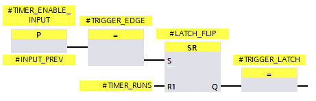
Input positive-edge detector and latched logical gateway
This procedure accepts the input, detects a positive edge, and then executes the latched logical gate, feeding it also with a timer firing signal as a reset trigger. The TRIGGER_LATCH variable stores the timer start / auto-restart request flag.
Network 2. Timer Wrapper
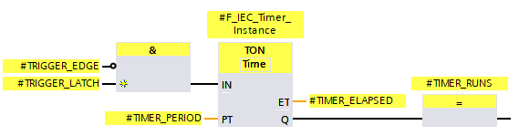
Timer wrapper with an input summator
This procedure summarises the feedback and converts it to actual timer start requests. The timer output is linked with the feedback loop via the TIMER_RUNS variable.
Output Muxers
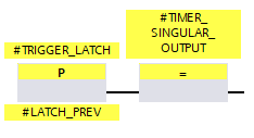
Network 3. Output muxer: singular
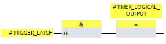
Network 4. Output muxer: pure logical
These networks are producing the actual function block outputs.
Additional Network 5. Counter Increment Request
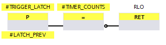
Counter Signal Processor
This additional network produces the counter synchronisation pulse and then decides if the internal counter should be incremented right now. The optional output TIMER_COUNTS is used to propagate the produced pulse.
Additional Network 6. Counter Increment Command
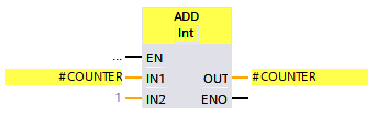
Counter Increment Command
This network uses the optional reference name COUNTER to have a memory cell for the counter.
The fully formulated failsafe function block could be used identically with the SE legacy timer (in a truncated variant), or as an extended timer with an embedded counter. In its extended variant, it can be used easily to handle any normally-closed input signals.